Home Automation Using Node-Red and Arduino
This is still a work in progress and will continue to be updated!
I've finally started my home automation project. This is a rundown of how I'm making it happen and some of the problems I encountered along the way.
The hardware involved includes:
- Raspberry Pi 3B with touchscreen
- Many Wemos D1 Minis with various shields
- Various sensors relays and other components
First install Mosquitto.
sudo apt-get update
sudo apt-get upgrade
sudo apt-get dist-upgrade
sudo apt-get install mosquitto mosquitto-clients
It should start every time the Pi boots. You also have to make Node-Red run at boot by running this command on the Raspberry Pi.
sudo systemctl enable nodered.service
The front end for this system is Node-Red Dashboard. This is an add-on for Node-Red that creates a user interface that's very configurable and easy to setup. Go to the menu in your Node-Red and click on "Manage palette" click the install tab and search for "node-red-dashboard" Once installed you'll have an interface at yourPi:1880/ui.


The node-red-dashboard has a ton of features. I urge you to explore a little bit and you'll easily have it looking exactly as you want it. It's easy to setup multiple pages and tabs to keep it all organized.
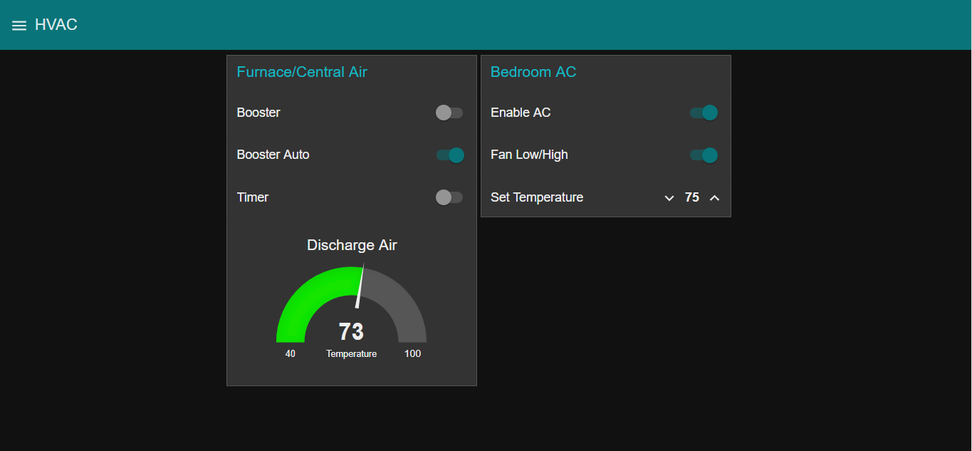
Here is a page I have setup for controlling a duct booster fan and a window air conditioner.

Here is what the flow looks like for the booster fan controls. It's setup with a simple on/off switch, an auto temperature controlled trigger and a timer. I'll go into what everything in the flow does after we go over the Arduino code and hardware setup.

The Hardware (photos soon)
- Wemos D1 Mini
- Relay Shield
- USB Charger
- DS18B20 Temperature Probe
- Inline HVAC Duct Booster
- Enclosure
The Software
- Arduino IDE
- Wemos D1 Board Definitions
- PubSubClient Library
- DallasTemperature Library
https://raw.githubusercontent.com/Lauszus/Sanguino/master/package_lauszus_sanguino_index.json
to the "Additional Boards Manager URLs:"
Then search for and install the PubSubClient library and the DallasTemperature library.
This is the sketch running on the D1. Remember to change it for your WiFi network and the mqtt topics you wish to use.
#include <OneWire.h>
#include <DallasTemperature.h>
#include <ESP8266WiFi.h>
#include <PubSubClient.h>
#define ONE_WIRE_BUS D4

const char* ssid = "SSID"; //replace with your SSID
const char* password = "PASSWORD"; //replace with your password
const char* mqtt_server = "MQTT_BROKER"; //replace with the address of your mqtt broker

WiFiClient espClient;
PubSubClient client(espClient);
OneWire oneWire(ONE_WIRE_BUS);
DallasTemperature sensors(&oneWire);

long lastMsg = 0;
char msg[50];
int value = 0;
int rly = D1;
int temp = 0;

void setup() {
  pinMode(BUILTIN_LED, OUTPUT);
  digitalWrite(BUILTIN_LED, 1);
  pinMode(rly, OUTPUT);
  Serial.begin(9600);
  setup_wifi();
  client.setServer(mqtt_server, 1883);
  client.setCallback(callback);
  sensors.begin();
}

void setup_wifi() {

  delay(10);
  Serial.println();
  Serial.print("Connecting to ");
  Serial.println(ssid);

  WiFi.begin(ssid, password);

  while (WiFi.status() != WL_CONNECTED) {
    delay(500);
    Serial.print(".");
  }

  Serial.println("");
  Serial.println("WiFi connected");
  Serial.println("IP address: ");
  Serial.println(WiFi.localIP());
}

void callback(char* topic, byte* payload, unsigned int length) {
  Serial.print("Message arrived [");
  Serial.print(topic);
  Serial.print("] ");
  for (int i = 0; i < length; i++) {
    Serial.print((char)payload[i]);
  }
  Serial.println();
   if ((char)payload[0] == '1') {
    digitalWrite(rly, 1);
  } else if ((char)payload[0] == '0') {
    digitalWrite(rly, 0);
  }
}

void reconnect() {
  while (!client.connected()) {
    Serial.print("Attempting MQTT connection...");
    // Attempt to connect
    if (client.connect("ESP8266Boost")) {   //remember each device in your setup must have it's own client name
      Serial.println("connected");
      client.subscribe("boost0");           //topic sent by broker
    } else {
      Serial.print("failed, rc=");
      Serial.print(client.state());
      Serial.println(" try again in 5 seconds");
      delay(5000);
    }
  }
}
void loop() {

  if (!client.connected()) {
    reconnect();
  }
  client.loop();

  sensors.requestTemperatures();
  temp = sensors.getTempFByIndex(0);

  long now = millis();
  if (now - lastMsg > 1000) {
    lastMsg = now;
    Serial.print("Temperature for the device 1 (index 0) is: ");
    Serial.println(sensors.getTempFByIndex(0));
    client.publish("dat0", String(temp).c_str(), true);  //publishes temperature to topic dat0
  }
}


Comments
Post a Comment