Dual 7 Segment Display
This is another Instructable I created a while back.
I created a dual 7 segment led display controlled by an Arduino through two 8-bit shift registers. The bonus is that it only uses 3 of the Arduino's pins. Instead of using 14 resistors for the leds I used a voltage regulator to drop the voltage to 2.1v mostly so I would't have to solder all those resistors.
Materials:


We'll be running the leds and the shift registers off of 2.1 volts from the lm317. This means we wont need to use resistors on the leds. I used a calculator I found here to get the resistor values. R1 is 240ohm and R2 is 160ohm. You can use the calculator to find other resistor combinations. You also need to put a .1μF capacitor on the Vin and a 1μF capacitor on the Vout. I soldered these components in the corner of the breadboard and left wire leads from the Vin and Ground.
Here's the schematic to wire everything up.

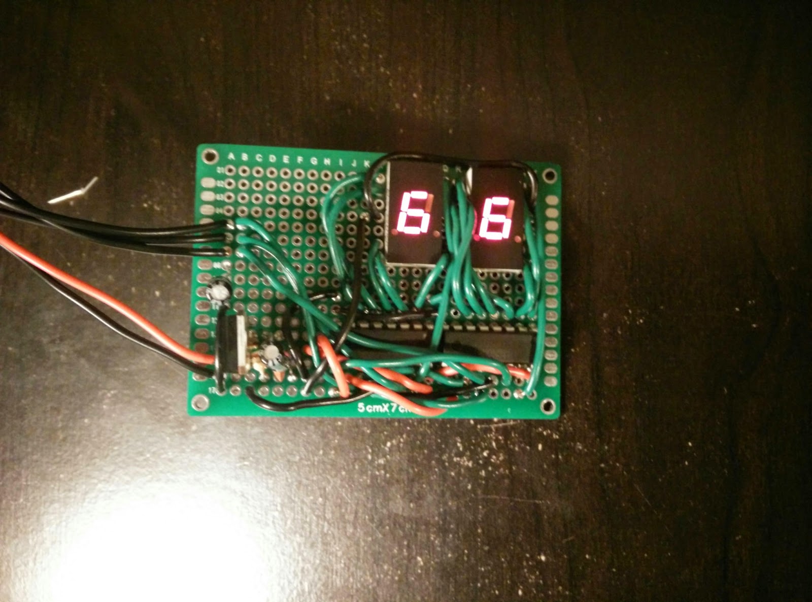
I soldered everything to a perf board. My shift registers outputs were labeled A through H so I connected them A to A on the 7 segment display, B to B and so on. I didn't use H, I may connect this later though. I believe it's for the decimal point but these displays have two decimal points so I'm not sure how that works. Each shift register controls it's own 7 segment display. The serial output from the first shift register goes to the serial input on the second. Both clock pins and both latch pins get tied together. I soldered 3 leads on the edge of the board for serial, clock and latch.
Next you have to find the hex value for all the digits.


I added a DHT11 connected to pin 7 and used the display to show the temperature and humidity. You'll notice there's some tricky math to separate the two digits of each value before sending them to the display. I also added values to display an F, h and -.
I created a dual 7 segment led display controlled by an Arduino through two 8-bit shift registers. The bonus is that it only uses 3 of the Arduino's pins. Instead of using 14 resistors for the leds I used a voltage regulator to drop the voltage to 2.1v mostly so I would't have to solder all those resistors.
Materials:
- 1 x small breadboard
- 1 x lm317 voltage regulator
- 2 x common cathode 7 segment led display
- 2 x 74hc595 8-bit shift register
- 1 x 240 ohm resistor
- 1 x 160 ohm resistor
- 1 x .1μF capacitor
- 2 x 1μF capacitor
- A bunch of wire
- Soldering Iron
- Solder
We'll be running the leds and the shift registers off of 2.1 volts from the lm317. This means we wont need to use resistors on the leds. I used a calculator I found here to get the resistor values. R1 is 240ohm and R2 is 160ohm. You can use the calculator to find other resistor combinations. You also need to put a .1μF capacitor on the Vin and a 1μF capacitor on the Vout. I soldered these components in the corner of the breadboard and left wire leads from the Vin and Ground.
Here's the schematic to wire everything up.
I soldered everything to a perf board. My shift registers outputs were labeled A through H so I connected them A to A on the 7 segment display, B to B and so on. I didn't use H, I may connect this later though. I believe it's for the decimal point but these displays have two decimal points so I'm not sure how that works. Each shift register controls it's own 7 segment display. The serial output from the first shift register goes to the serial input on the second. Both clock pins and both latch pins get tied together. I soldered 3 leads on the edge of the board for serial, clock and latch.
Next you have to find the hex value for all the digits.
To find the values for the digits I made a chart for H through A, this is the order they will be sent to the shift register.
Each digit must have a 0 or 1 assigned for each section H through A. For example a 2 would be 01011011. Then you split the code into 4 bit sets, 0101 and 1011. Then I used the chart to convert this to a hex value. So the hex code for the digit 2 is 0x5B. I did this for all the digits 0 through 9. This is included in the code in the next step.
Finally, some code to make it all work.
The first sketch simply counts from 00 through 99 in a loop. Connect the two power leads from the board to +5v and Ground on the Arduino and the Seral, Clock and Latch pins from the board to pins 2, 3 and 4 on the Arduino.
Now to make it do something useful.Each digit must have a 0 or 1 assigned for each section H through A. For example a 2 would be 01011011. Then you split the code into 4 bit sets, 0101 and 1011. Then I used the chart to convert this to a hex value. So the hex code for the digit 2 is 0x5B. I did this for all the digits 0 through 9. This is included in the code in the next step.
Finally, some code to make it all work.
The first sketch simply counts from 00 through 99 in a loop. Connect the two power leads from the board to +5v and Ground on the Arduino and the Seral, Clock and Latch pins from the board to pins 2, 3 and 4 on the Arduino.
I added a DHT11 connected to pin 7 and used the display to show the temperature and humidity. You'll notice there's some tricky math to separate the two digits of each value before sending them to the display. I also added values to display an F, h and -.


Comments
Post a Comment